Series / Product
5935 Series Straight Run Belt
5935 Series Straight Run Belt for industrial conveying and replacement work, with series-specific dimensions, interface checks and RFQ guidance.
- Pitch
- 19.05 mm
- Minimum backflex radius
- 25 mm
- Maximum working load at 21°C
- 13,000 N for XLG/PS; 7,000 N for XP
- Working temperature, XLG/PS
- 4–65 °C dry/wet
For replacement work, send the existing series/model when known plus measured width, pitch and drive-interface details. Unknown values can remain open for confirmation.
Product overview
5935 Series Straight Run Belt is presented as an industrial conveyor component for OEM, replacement and line-development work. This page keeps the series identity and available technical data together, then explains the surrounding interfaces that determine whether a replacement or new installation will fit and run correctly.
A plastic modular conveyor is a positive-drive system. The belt or chain should be selected as part of a complete mechanical interface that includes the conveyed product, support surface, shaft arrangement, sprocket position, return path, guides, transfers, temperature, cleaning regime, and accumulation behavior. A small geometric mismatch can alter articulation or tooth engagement, so purchasing decisions should be based on measured interfaces rather than visual similarity alone. For replacement work, the most useful starting information is the existing belt or chain identification, pitch, assembled width, hinge or rod arrangement, edge profile, sprocket tooth count, sprocket bore, shaft size, and clear photographs of the drive and return ends. When a legacy marking is unreadable, a dimensioned sketch and several perpendicular photographs are more reliable than one perspective image.
Structure and interface
Straight-running and radius systems impose different geometric demands. Straight-running modules articulate around sprockets in the travel direction, while a radius or side-flexing design must also accommodate lateral articulation through a controlled curve. A straight belt should never be forced through a curve simply because its width fits the frame.
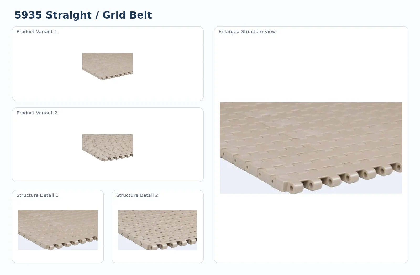
Check the hinge line, edge geometry, underside drive features and any retention elements against the existing system. Do not identify the product from color alone.
Technical specifications
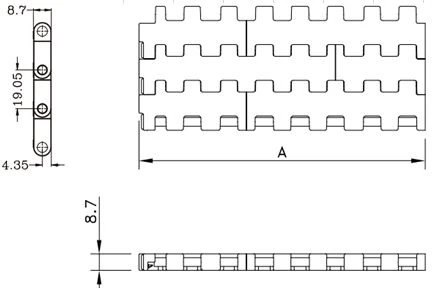
Use the series-specific values below when checking fit, operating conditions and drive compatibility. Confirm project conditions before release.
| Parameter | Value |
|---|---|
| Pitch | 19.05 mm |
| Minimum backflex radius | 25 mm |
| Maximum working load at 21°C | 13,000 N for XLG/PS; 7,000 N for XP |
| Working temperature, XLG/PS | 4–65 °C dry/wet |
| Working temperature, XP | 4–105 °C dry/wet |
| Weight | 6.3 kg/m² XLG/PS; 4.9 kg/m² XP |
| Mold-part widths | 76.2 / 152.4 mm |
| Standard assembly width | W = 76.2 × N |
Selection checks
Confirm straight, radius, incline, accumulation and transfer duty.
Measure pitch, assembled width, hinge/rod position and any retention features.
Confirm compatible sprocket series, tooth count, bore and shaft.
State temperature, wet/dry duty, cleaning chemistry and special material needs.
Operating environment matters because thermoplastic materials respond differently to temperature, moisture, chemicals, abrasion, and continuous sliding contact. Published series values should be used together with their stated material codes and temperature ranges. A material should not be substituted solely because it has a similar color; color is not a sufficient material identification method.
Application planning
The series must be reviewed with product footprint, load, stability, speed, transfer sensitivity, accumulation and cleaning access. For curves, the side-flexing geometry and guide path become part of the selection. For straight conveyors, support and drive alignment remain equally important.
Transfers deserve the same engineering attention as the long conveyor span. Small or unstable products may need a comb plate, roller bridge, nose arrangement, or controlled dead-plate geometry. The objective is not merely a small visible gap; the interface must support the product and avoid interference between moving modules and stationary parts.

Drive and sprocket matching
Sprockets provide the positive-drive relationship. Tooth count, pitch diameter, bore, hub or split construction, shaft keying, and axial location should be reviewed together. Poor alignment can concentrate load on only part of the belt width, while an inappropriate fixing arrangement can interfere with thermal movement.
Installation and commissioning
Before installation, inspect guides, supports, shafts, sprockets and transfer parts for wear or interference. Fit the belt or chain without forcing joints. Rotate the drive slowly or jog the machine at low speed to confirm clean tooth engagement across the width, stable guide contact and a controlled return path.
After loading representative product, observe transfers, curves, accumulation zones and any incline. Repeated impact, local lifting, scraping or a change in drive noise usually deserves mechanical investigation before continued production.
Inspection and maintenance
Maintenance is most effective when it is inspection-led. Operators should monitor hinge areas, rods, guide contact, sprocket engagement, unusual noise, local wear, product buildup, and any change in the return path. Replacing one worn component without correcting alignment or contamination may only move the problem to another location.
Cleaning or sanitation methods should be compatible with the selected material and with rollers, elastomers, magnets or retention features on the exact series.
RFQ preparation
For OEM and retrofit projects, a good RFQ separates confirmed data from open questions. Confirmed dimensions should be listed with units and measurement method. Unknown material, load, speed, or chemical exposure should be marked for confirmation rather than estimated.
- Series or existing marking
- Pitch and assembled width
- Overall conveyor layout and curve direction
- Sprocket tooth count, bore and shaft
- Product load, speed, temperature and wet/dry conditions
- Quantity and sample/replacement/OEM status
Frequently asked questions
Can a replacement be selected from a photograph alone?
Photos help with identification, but pitch, width, hinge/rod geometry and the drive interface should also be measured.
Do existing sprockets need replacement?
Not always. Check series compatibility, tooth condition, bore/shaft fit and wear before reusing them.
Can material be changed independently of geometry?
Material changes can alter temperature capability, friction and wear. Use the listed options as the starting point and request confirmation for alternatives.
How should non-standard width be requested?
Send the required assembled width and the measured module increment or an existing sample. Width rules differ by series.
What speeds the quotation?
Series, pitch, width, sprocket/shaft data, application, operating conditions, quantity and drawings or clear photos.
Fit and release checks for this series
Use the available series dimensions together with the actual conveyor interfaces. The final release should identify what is confirmed and what still needs measurement.
Confirm pitch, assembled width, hinge or rod layout and underside drive features.
Verify straight-running, transfer, accumulation or process requirements before release.
Record compatible sprocket or mounting geometry, shaft/bore information and the condition of existing mating components.
State product, load, speed, temperature, moisture, cleaning, accumulation and transfer conditions that apply to this project.
Confirmed series data to carry into the RFQ
Pitch: 19.05 mm; Minimum backflex radius: 25 mm; Maximum working load at 21°C: 13,000 N for XLG/PS; 7,000 N for XP; Working temperature, XLG/PS: 4–65 °C dry/wet; Working temperature, XP: 4–105 °C dry/wet; Weight: 6.3 kg/m² XLG/PS; 4.9 kg/m² XP. Use these values only for the exact series shown on this page; any project-specific dimension or alternative material should be confirmed before ordering.
For a replacement, add photographs of the existing top surface, underside, edge/hinge area, drive sprockets and return end. For a new machine, add the conveyor layout and the product path so support, guides and transfers can be reviewed with the selected component.
How to apply the series data on the machine
The listed values define the series, while the conveyor decides whether that series is appropriate for the project.
Machine fit
Review the belt or chain as part of the complete carryway. Confirm support, drive alignment, return path and transfer clearances before the final width or series is released.
Useful confirmed values on this page include pitch 19.05 mm, minimum backflex radius 25 mm, maximum working load at 21°c 13,000 N for XLG/PS; 7,000 N for XP, working temperature, xlg/ps 4–65 °C dry/wet, working temperature, xp 4–105 °C dry/wet. Keep the unit and the exact parameter name with the purchasing record so the value is not separated from its meaning.
Inspection focus
Localized wear, irregular engagement, repeated noise or edge contact can indicate a machine-interface issue rather than a material issue in the moving component itself.
Before reusing surrounding parts, clean and inspect the mating surfaces and drive elements. Photograph any abnormal wear before disassembly; the wear pattern can help explain why the previous component failed or became unstable.
| Check | Practical review |
|---|---|
| Existing machine | Measure the part and the surrounding conveyor independently. Do not assume a worn component still shows the original nominal dimension. |
| New machine | Confirm machine envelope, support, drive, transfer and service access before final series release. |
| Alternative option | If material or configuration may change, state which machine dimensions are fixed and which product variables are flexible. |
| Purchase record | Keep series, width, drive/mounting data, operating conditions and any accepted drawing revision together. |
Commissioning record for 5935 Series Straight Run Belt
Confirm assembly, belt or chain seating, drive/mounting alignment and clearance to stationary parts. Rotate or jog slowly when the machine permits.
Use representative product and observe the most demanding zone: curve, accumulation, incline, transfer or return support as applicable.
Check for localized wear, new noise, edge contact, rod movement, product marks or debris concentration. Record the location of any abnormality.
Keep the final series, installed width, mating component data and operating condition with the maintenance record for future replacement.
Additional series data carried on this page includes Working temperature, XP: 4–105 °C dry/wet; Weight: 6.3 kg/m² XLG/PS; 4.9 kg/m² XP; Mold-part widths: 76.2 / 152.4 mm; Standard assembly width: W = 76.2 × N. Do not detach these values from the exact series or configuration when preparing a purchase description. If the machine requires a different width, material, mounting or drive arrangement, flag the change for confirmation rather than treating it as an automatic option.
Request a series-level quotation
Send the series/model when known, measured dimensions, drive or mounting data, operating conditions, quantity and drawings or photographs. Open points can remain explicit until confirmed.