Answer first
- Confirm the measurable interface before choosing a replacement.
- Keep series-specific published series limits with the exact material and geometry.
- Record any unknown value as an RFQ confirmation item rather than estimating it.
The safest approach to modular belt sprocket selection is to treat belt, chain, sprockets, support, guides, transfers and environment as one system. Start with measured geometry and duty conditions, eliminate incompatible configurations, and only then finalize material and accessories.
1. Define product and process
Record product dimensions, weight, base shape, temperature, stability and whether accumulation is expected. Add the process requirement: washing, draining, cooling, heating, inspection, buffering, merging or transport.
Operating environment matters because thermoplastic materials respond differently to temperature, moisture, chemicals, abrasion, and continuous sliding contact. Published series values should be used together with their stated material codes and temperature ranges. A material should not be substituted solely because it has a similar color; color is not a sufficient material identification method.
2. Define conveyor geometry
Straight-running and radius systems impose different geometric demands. Straight-running modules articulate around sprockets in the travel direction, while a radius or side-flexing design must also accommodate lateral articulation through a controlled curve. A straight belt should never be forced through a curve simply because its width fits the frame.
Measure straight lengths, incline angle, curve angle, inner radius, conveyor width, shaft centerline, transfer heights and return path.
3. Measure existing belt or chain
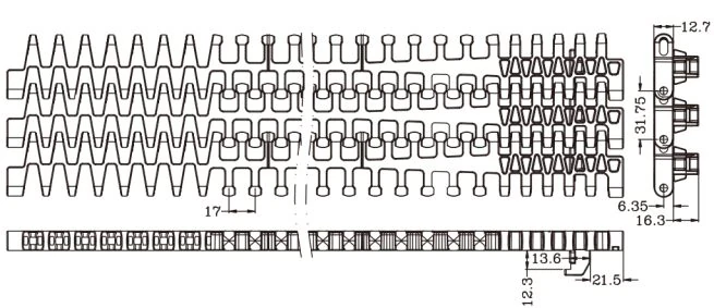
For replacement work, the most useful starting information is the existing belt or chain identification, pitch, assembled width, hinge or rod arrangement, edge profile, sprocket tooth count, sprocket bore, shaft size, and clear photographs of the drive and return ends. When a legacy marking is unreadable, a dimensioned sketch and several perpendicular photographs are more reliable than one perspective image.
4. Match the positive drive
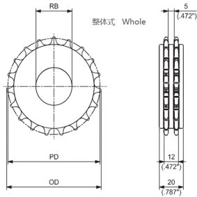
Sprockets provide the positive-drive relationship. Tooth count, pitch diameter, bore, hub or split construction, shaft keying, and axial location should be reviewed together. Poor alignment can concentrate load on only part of the belt width, while an inappropriate fixing arrangement can interfere with thermal movement.
5. Review support, guides and transfers
Transfers deserve the same engineering attention as the long conveyor span. Small or unstable products may need a comb plate, roller bridge, nose arrangement, or controlled dead-plate geometry. The objective is not merely a small visible gap; the interface must support the product and avoid interference between moving modules and stationary parts.
| Interface | Engineering check |
|---|---|
| Carry-way support | Support surface must suit module geometry and load. |
| Return path | Prevent uncontrolled sag or interference. |
| Guides | Control product without forcing belt/chain outside its intended path. |
| Transfer | Check comb, roller bridge or dead-plate clearance. |
| Drive | Confirm clean tooth engagement and alignment. |
6. Commission and maintain
Maintenance is most effective when it is inspection-led. Operators should monitor hinge areas, rods, guide contact, sprocket engagement, unusual noise, local wear, product buildup, and any change in the return path. Replacing one worn component without correcting alignment or contamination may only move the problem to another location.
Record the final installed series, sprocket data, shaft arrangement, key dimensions and any special material or cleaning requirement.
RFQ checklist
For OEM and retrofit projects, a good RFQ separates confirmed data from open questions. Confirmed dimensions should be listed with units and measurement method. Unknown material, load, speed, or chemical exposure should be marked for confirmation rather than estimated.
Frequently asked questions
Which dimension should I measure first?
Start with pitch and assembled width, then document the hinge/rod line, belt edge and sprocket/shaft interface.
Can a drawing be scaled from a photograph?
Not reliably unless a scale exists in the same plane. Use direct measurement whenever possible.
What if the part has no readable marking?
Send multiple photos, pitch, width, underside drive geometry, sprocket tooth count and bore, and a sample if possible.
Should material be changed when the old belt wears quickly?
Identify the wear mechanism first. Alignment, support, contamination and temperature may be more important than material.
How do I compare two candidates?
Compare geometry, surface function, load, temperature, width construction, radius/backflex limits and sprocket/component requirements.
Decision record before release
| Decision point | What to verify |
|---|---|
| Geometry | Write down pitch, width, hinge/rod or edge details and the specific running geometry. Separate measured values from nominal assumptions. |
| Drive | Identify sprocket family, tooth count, bore, shaft size and how sprockets are fixed or allowed to float axially. |
| Process | Record product load, speed, temperature, cleaning, moisture, accumulation and transfer conditions that can change surface or material choice. |
| Open points | List every unknown explicitly and close it through measurement, drawing review, sample comparison or supplier confirmation before ordering. |
A useful engineering record is short enough to be maintained but complete enough that another engineer can repeat the decision. It should state what was measured, what was selected, which interfaces were checked and which conditions still need confirmation.
Worked decision sequence for sprocket selection
Use the sequence below as a review order. It keeps machine geometry ahead of appearance and keeps operating conditions attached to the component choice.
Record belt series/pitch and identify which surrounding dimensions are fixed by the existing machine or proposed layout.
Measure or define tooth count and bore/shaft with units, drawings or clear photographs.
Check keyway or idler fit together with product behavior, speed, temperature, moisture, cleaning and accumulation where relevant.
Confirm axial position, mating components and all open RFQ points before the final order description is frozen.
How to compare two candidate configurations
| Check | Practical review |
|---|---|
| Geometry | Reject a candidate that does not match the required articulation, pitch, width, bore, guide or mounting interface even if other features appear attractive. |
| Operating envelope | Compare temperature, wet/dry duty, load, cleaning and process conditions only for the exact material/configuration being considered. |
| Mating components | Include sprockets, shafts, guides, wear strips, return parts and transfers in the comparison. A lower-cost moving component may require changes elsewhere. |
| Maintenance | Compare access to hinges/rods, drive and return components, cleaning zones and the practical method of replacing wear parts. |
| Documentation | Prefer the option that can be released with a clear series, dimensions, material/configuration and mating-interface record. |
What an inspection can tell you
Existing wear can reveal whether the previous configuration was loaded evenly. Edge polishing, local sprocket wear, repeated guide marks, rod movement, debris concentration or a change in transfer damage can identify where to measure next. Treat these observations as diagnostic clues rather than as proof that the belt material itself is wrong.
When several symptoms occur together, start with alignment and interface geometry. Correcting the root cause before installing a replacement helps avoid transferring the same problem to a new component.
Record before disassembly
- Drive and return-end photographs
- Guide and wear-strip contact areas
- Transfer geometry and product orientation
- Any localized wear or discoloration
- Measurements with units and measurement point
Send the engineering data
Provide the measured interfaces, application conditions and current component details. Unknown values can remain explicit until they are confirmed.