Rispondi prima
- Prima di scegliere un sostituto, verificare l'interfaccia misurabile.
- Rispettare i limiti di serie pubblicati specifici per la serie, utilizzando esattamente lo stesso materiale e la stessa geometria.
- Registra qualsiasi valore sconosciuto come elemento di conferma della richiesta di offerta, anziché stimarlo.
The safest approach to how belt surface changes product contact, drainage, transfer and traction is to treat belt, chain, sprockets, support, guides, transfers and environment as one system. Start with measured geometry and duty conditions, eliminate incompatible configurations, and only then finalize material and accessories.
1. Definire il prodotto e il processo
Registrare le dimensioni del prodotto, il peso, la forma della base, la temperatura, la stabilità e se è previsto un accumulo. Aggiungere il requisito del processo: lavaggio, drenaggio, raffreddamento, riscaldamento, ispezione, tamponamento, miscelazione o trasporto.
L'ambiente operativo è importante perché i materiali termoplastici reagiscono in modo diverso a temperatura, umidità, agenti chimici, abrasione e contatto di scorrimento continuo. I valori di serie pubblicati devono essere utilizzati insieme ai relativi codici materiale e intervalli di temperatura. Un materiale non deve essere sostituito solo perché ha un colore simile; il colore non è un metodo sufficiente per l'identificazione del materiale.
2. Definire la geometria del trasportatore
I sistemi a cinghia rettilinea e a raggio impongono esigenze geometriche diverse. I moduli a cinghia rettilinea si articolano attorno alle ruote dentate nella direzione di marcia, mentre un design a raggio o a flessione laterale deve anche consentire l'articolazione laterale attraverso una curva controllata. Una cinghia rettilinea non dovrebbe mai essere forzata a passare attraverso una curva semplicemente perché la sua larghezza si adatta al telaio.
Misurare le lunghezze rettilinee, l'angolo di inclinazione, l'angolo di curvatura, il raggio interno, la larghezza del trasportatore, l'asse centrale dell'albero, le altezze di trasferimento e il percorso di ritorno.
3. Misurare la cinghia o la catena esistente
Per i lavori di sostituzione, le informazioni di partenza più utili sono l'identificazione della cinghia o catena esistente, il passo, la larghezza assemblata, la disposizione delle cerniere o delle aste, il profilo del bordo, il numero di denti della ruota dentata, il foro della ruota dentata, la dimensione dell'albero e fotografie nitide delle estremità di trasmissione e di ritorno. Quando una marcatura preesistente è illeggibile, uno schizzo quotato e diverse fotografie perpendicolari sono più affidabili di una singola immagine prospettica.
4. Abbinare la spinta positiva
Le ruote dentate garantiscono la trasmissione del moto. Il numero di denti, il diametro primitivo, il foro, la costruzione del mozzo o a cinghia sdoppiata, la chiavetta dell'albero e la posizione assiale devono essere valutati congiuntamente. Un allineamento errato può concentrare il carico solo su una parte della larghezza della cinghia, mentre un sistema di fissaggio inadeguato può interferire con la dilatazione termica.
5. Esamina supporto, guide e trasferimenti
I trasferimenti meritano la stessa attenzione ingegneristica riservata alle lunghe campate del nastro trasportatore. Prodotti piccoli o instabili possono richiedere una piastra a pettine, un ponte a rulli, una configurazione del naso o una geometria controllata della piastra fissa. L'obiettivo non è semplicemente quello di creare un piccolo spazio visibile; l'interfaccia deve supportare il prodotto ed evitare interferenze tra i moduli in movimento e le parti fisse.
| Interfaccia | Controllo tecnico |
|---|---|
| Supporto per il trasporto | La superficie di appoggio deve essere adatta alla geometria del modulo e al carico. |
| percorso di ritorno | Evitare cedimenti o interferenze incontrollate. |
| Guide | Controllare il prodotto senza forzare la cinghia/catena al di fuori del suo percorso previsto. |
| Trasferire | Verificare il gioco tra pettine, ponte a rulli o piastra di fissaggio. |
| Guidare | Verificare la corretta interazione e l'allineamento dei denti. |
6. Commissionare e mantenere
La manutenzione è più efficace quando è guidata dall'ispezione. Gli operatori devono monitorare le aree delle cerniere, le aste, il contatto delle guide, l'innesto delle ruote dentate, rumori insoliti, usura localizzata, accumulo di prodotto e qualsiasi cambiamento nel percorso di ritorno. Sostituire un componente usurato senza correggere l'allineamento o la contaminazione potrebbe semplicemente spostare il problema in un altro punto.
Registrare la serie finale installata, i dati del pignone, la disposizione dell'albero, le dimensioni principali e qualsiasi requisito speciale relativo al materiale o alla pulizia.
Lista di controllo della richiesta di offerta (RFQ)
Per i progetti OEM e di retrofit, una buona richiesta di offerta (RFQ) separa i dati confermati dalle questioni aperte. Le dimensioni confermate devono essere elencate con unità di misura e metodo di misurazione. Materiali, carichi, velocità o esposizione a sostanze chimiche sconosciuti devono essere indicati come dati da confermare, anziché essere stimati.
Domande frequenti
Quale dimensione dovrei misurare per prima?
Iniziate definendo il passo e la larghezza assemblata, quindi documentate la linea cerniera/asta, il bordo della cinghia e l'interfaccia pignone/albero.
È possibile realizzare un disegno in scala a partire da una fotografia?
Non è affidabile a meno che non esista una scala sullo stesso piano. Utilizzare la misurazione diretta ogni volta che è possibile.
Cosa succede se il pezzo non presenta marcature leggibili?
Invia più foto, passo, larghezza, geometria della trasmissione inferiore, numero di denti della ruota dentata e foro, e se possibile un campione.
È opportuno sostituire il materiale della cinghia quando si usura rapidamente?
Innanzitutto, individua il meccanismo di usura. Allineamento, supporto, contaminazione e temperatura possono essere più importanti del materiale.
Come posso confrontare due candidati?
Confrontare geometria, funzione della superficie, carico, temperatura, costruzione della larghezza, limiti di raggio/flessione all'indietro e requisiti di pignone/componente.
Decision framework
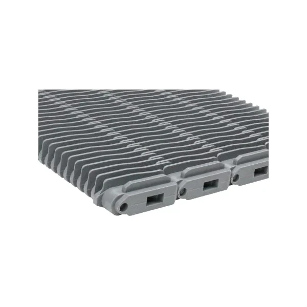
Flat Top, Grid, Raised Rib and Roller Top Belt Surfaces Explained: what the engineering review must decide
Treat the topic as an interface decision. For this topic, the central issue is surface function and product-handling behavior. A component can look correct yet still fail the dimensional or operating checks that control real fit. The project record should connect the visible condition, the measured interface and the operating duty so that a proposed series can be checked against the same evidence later.
Start by identifying which parts of the system are fixed by the machine and which are still open to selection. A shaft, guide path, transfer location or process envelope may be fixed, while material, surface, exact series or component configuration can remain open. Making that distinction early prevents the engineering discussion from treating every catalogue option as interchangeable.
| Decision variable | What to document |
|---|---|
| product footprint and base stiffness | Record the project value or condition and note how it was confirmed before release. |
| surface type and contact area | Record the project value or condition and note how it was confirmed before release. |
| accumulation or transfer duty | Record the project value or condition and note how it was confirmed before release. |
| incline/traction requirement | Record the project value or condition and note how it was confirmed before release. |
| cleaning and debris release | Record the project value or condition and note how it was confirmed before release. |
Field method
Measure the interfaces that control this decision
For surface function and product-handling behavior, the most useful field record covers product base dimensions, contact pattern, transfer gap, incline angle when applicable and the location where sliding, rolling or gripping is expected. Measurements should be taken on a clean, supported component whenever possible. If wear is present, record the worn condition and avoid treating it as the original nominal geometry.
Use direct dimensions with units and take more than one reading when wear, articulation or assembly tolerances can affect the result. A photograph should show the measuring tool in the same plane as the feature being checked; a second perpendicular photograph provides context that a single perspective image cannot. When a dimension cannot be obtained reliably, mark it as open rather than estimating it.
The machine layout matters as much as the loose part. Record the drive end, return end, guide arrangement, transfer zone and any location where the belt changes direction or experiences unusual product pressure. That context explains why two parts with similar overall dimensions may behave differently in service.

Troubleshooting
Interpret the symptom before changing the component
Wear is evidence of a contact or operating condition. Use the pattern to decide what to inspect next rather than replacing the most visible worn part automatically.
Compare measurable geometry before accepting a visual match: pitch, assembled width, hinge or rod line, underside drive features and edge profile. Appearance can narrow identification, but it cannot establish interchangeability.
Observe the line during the actual accumulation state. Record where products begin to contact, how long they remain accumulated, and whether sliding, roller action, guides or transfer geometry changes the pressure path.
Verify the roller axis against the intended product motion and transfer direction. Check that the roller is supported and free to rotate, and that the receiving conveyor or guide does not oppose the intended movement.
Check the raised or high-friction surface against the real product base, incline, cleaning method and transfer clearance. Extra grip is useful only when the protruding surface does not create release, hygiene or interference problems elsewhere.
A single symptom rarely proves the root cause. Compare left and right sides, drive and return zones, loaded and unloaded operation, and the condition of mating parts. If a problem appears only after product accumulation, washdown, temperature change or a line-speed change, include that operating state in the investigation. This is especially important when the existing system ran acceptably before a process change.
Machine integration
Review the complete conveyor around the selected item
Use a simple sequence: confirm the product path, identify the belt or chain motion type, verify the positive-drive or mounting interface, review carry-way and return support, then check guides and transfers. The order matters because a change made to solve one zone can create a new interference or wear point elsewhere.
For this article, a representative review scenario is a packaging line comparing stable transport, accumulation and transfer behavior for cartons or containers with different base shapes. The technical review should therefore include the most demanding zone, not only the longest straight span. Where the product changes direction, accumulates, enters a transfer or experiences washdown, note the local geometry and the component that carries or constrains the load.
Keep safety guarding, access and the machine maker’s procedures outside the component-selection assumptions. The conveyor component data can support fit and operating review, but machine-level safety and commissioning remain part of the equipment design and site procedure.
Worked review
How to compare alternatives without inventing missing data
Assume the current line has a known product path and an existing component that may need replacement. First, write down the values that are physically measured or clearly identified. Next, list the parameters that come from the exact candidate series. Keep those two groups separate. A published material or operating value belongs to the candidate series; a shaft diameter, guide spacing or installed width belongs to the machine.
Then compare the fixed interfaces with each candidate. Reject an option when a required geometry is incompatible rather than trying to compensate with guide pressure, forced articulation or an improvised sprocket. If several options remain, compare the functional differences that matter to the process: contact surface, open area, rolling or gripping function, curve capability, transfer behavior, cleaning access or component serviceability. The choice should be traceable to the process requirement rather than to color or appearance.
Finally, identify what would still have to be confirmed before order release. The open item might be a material requirement, a drawing dimension, a bore/keyway detail, an exact installed width or an operating exposure. State who will confirm it and by what evidence. This makes the quotation useful even before every question is closed and avoids hiding uncertainty inside an assumed specification.
Procurement handoff
Build a purchase description that can be checked later
The handoff should preserve the relationship between the selected component and the machine. For this topic, keep surface family, product data, transfer/accumulation requirement, line geometry and any matching transfer component together in the RFQ or purchase record. Attach the layout or photographs used for the decision and identify any accepted alternative rather than relying on an informal description such as “same as existing.”
| Record | Purpose |
|---|---|
| Component identity | Series/model or the measured identification basis when the marking is unavailable. |
| Machine interface | Dimensions, shaft/mounting, guides, support, transfer and surrounding fixed geometry relevant to the topic. |
| Operating duty | Product/load, speed context, temperature, wet/dry condition, cleaning or other process exposure that affects selection. |
| Punti aperti | Items that still require a drawing, sample, second measurement or engineering confirmation. |
| Revision record | The final accepted drawing, series/configuration and any change from the previous installation. |
This record is also valuable for maintenance. If the conveyor is modified later, the team can see which assumptions belonged to the original selection and decide whether the changed product, speed, guide path, cleaning process or transfer geometry requires a fresh review.
Commissioning
Check the first run against the engineering assumptions
When the machine procedure permits, begin with an unloaded or lightly loaded check. Observe the drive or mounting interface, guide contact, carry-way support, return path and clearances to stationary parts. Then introduce representative product and watch the zone that drove the selection decision. The objective is to verify that the installed behavior matches the assumptions documented during selection.
Listen for new cyclic noise and inspect for localized rubbing, lifting, rod movement, edge contact, product marking or debris concentration. A small early change can be easier to correct before it becomes a wear pattern. Record the first inspection condition so later maintenance has a baseline rather than relying on memory.
If the result differs from the expected behavior, return to the measured interface and operating condition before changing material or series again. A component change cannot correct a misaligned shaft, an interfering guide or a transfer that physically constrains the belt outside its intended articulation.
Release checklist
Questions to close before ordering
- Is the exact motion type or component function identified?
- Are the controlling machine dimensions recorded with units?
- Are mating sprockets, shafts, guides, supports or transfer parts documented?
- Are product, load and operating conditions representative of actual duty?
- Are material or special-process requirements tied to the exact series rather than inferred?
- Are worn or modified surrounding parts identified separately from the proposed replacement?
- Are all unknown values explicitly listed for confirmation?
- Does the RFQ include quantity plus clear drawings, photographs or a sample when available?
Closing these questions produces a stronger engineering request and reduces the chance that a quotation is based on visual similarity alone. If a value remains unknown, leave it open and state the evidence needed to close it; do not invent a number to make the request appear complete.